A client of my company has purchased 3 HX Lenovo nodes and 2 ToR Cisco switches, each node was equipped with only 2 ports 10GbE (the LOM ones).
However, with only 2 ports, I don’t know how to setup the cluster in a way that there is a redundancy.
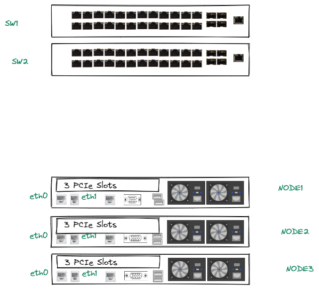
The current rack looks like this without any cabling yet:
The IPMI port will go to a Management Switch, so there’s no issue there. But so far, I am confused as to how setup the cabling for the two interfaces; Should eth0 go to a port on SW1 and eth1 go to a port on SW2 for each of the 3 servers? or should both eth0 and eth1 go to the same switch?
If I understood correctly the AHV Networking articles in Nutanix, eth0 and eth1 will form a logical bond (br0-up) inside the br0 bridge. And I’m guessing since we only have 2 uplinks per nodes (I’m going for the first scenario):
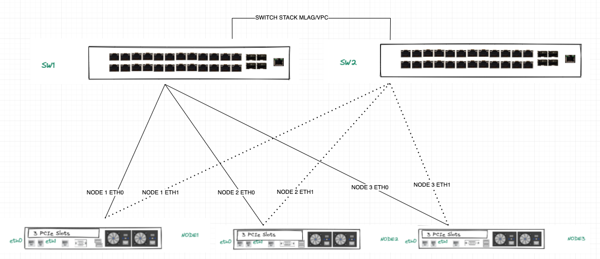
> eth0 will go to SW1Port1 (for example), SW1Port1 will be configured as a Trunk port, for which the CVM/AHV VLAN and User VMs VLANs will be declared.
> eth1 will go to SW2Port1, this port will have the same config as SW1Port1.
> eth0 and eth1 will be in the default active-standby br0-up bond post-Foundation set-up. (Except I’m assuming there won’t be no failover possible cause the adapters are connected to different switches?)
I’m aware this could be very simple but I’m just very confused. If anyone has an idea about how to best set this up. I would appreciate it. Thanks a lot!
Page 1 / 1
Hi @rockstershiny
I’ve seen your reddit post but i’ll be answering here.
For the answer i’ll assume that your switches are stacked/linked among them with MLAG/vPC or another fancy name. Also I’ not going to speak about the IPMI port because it will be plugged on independent management switches.
The IPMI port will go to a Management Switch, so there’s no issue there. But so far, I am confused as to how setup the cabling for the two interfaces; Should eth0 go to a port on SW1 and eth1 go to a port on SW2 for each of the 3 servers? or should both eth0 and eth1 go to the same switch?
You should always connect each nic to a different switch. If you have both nics plugged into the same switch and for whatever reason the switch dies, your node will loose connectivity with other nodes on the cluster and it will be marked as down (vm’s will be restarted on another healthy host and so on).
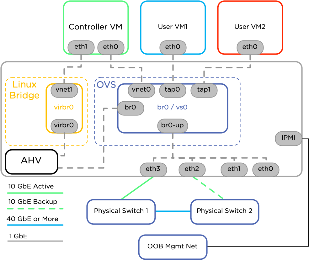
If I understood correctly the AHV Networking articles in Nutanix, eth0 and eth1 will form a logical bond (br0-up) inside the br0 bridge. And I’m guessing since we only have 2 uplinks per nodes
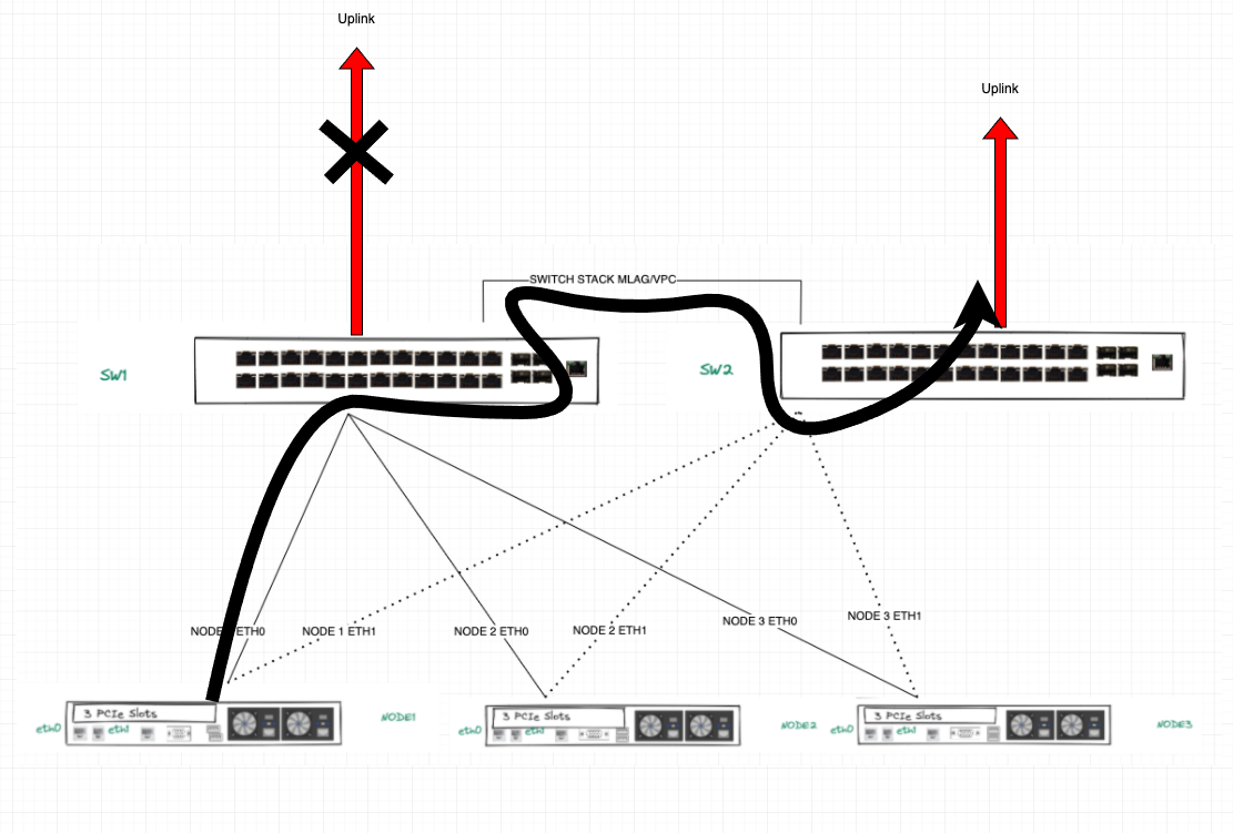
You are right, by default after foundation all nics belong to bridge br0 and bond br0-up. The diagram below shows 4 nic’s but you can get the idea.
eth0 will go to SW1Port1 (for example), SW1Port1 will be configured as a Trunk port, for which the CVM/AHV VLAN and User VMs VLANs will be declared.
> eth1 will go to SW2Port1, this port will have the same config as SW1Port1.
> eth0 and eth1 will be in the default active-standby br0-up bond post-Foundation set-up. (Except I’m assuming there won’t be no failover possible cause the adapters are connected to different switches?)
If you are using Active-Backup eth0 will be connected to switch 1 and eth 1 to switch 2. Both of them should be configured in the same way, Trunked. If switch 1 or eth0 dies the bond will switch immediately to switch 2 and eth1. This kind of configuration keeps things simple and just works but the maximum throughput will be 10G
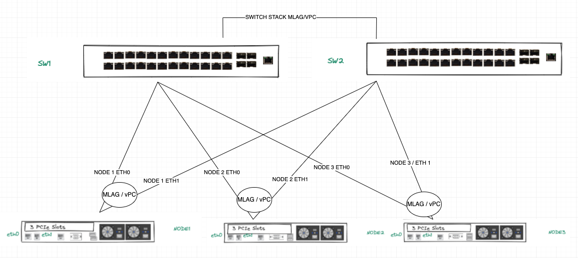
If you want to use the full bandwidth, 20G, the way to go is LACP aka balance-tcp. In this case you have to configure MLAG/vPC on the swithces and LACP on the bridges. Refer to your switch’s manual on how to set this up
By default bridge br0 is used for CVM traffic and UVM’s VLANS.
Also the recommendation is to configure the CVM/AHV hosts vlan as native or default vlan on the switch ports for ease of use. In other case you’ll have to manually change AHV and CVM VLAN’s
Hope this helps
Regards!
Hi @rockstershiny
I’ve seen your reddit post but i’ll be answering here.
Hope this helps
Regards!
Hi Bcaballero, I thank you so much for this detailed breakdown. It sure helped a lot to understand. One more question if I may, if we go with the default active-backup bond, and the switches have vPC configured between them, doesn’t that mean that the AHV hosts will have to be configured for LACP as well?
One more question if I may, if we go with the default active-backup bond, and the switches have vPC configured between them, doesn’t that mean that the AHV hosts will have to be configured for LACP as well?
Hello Reckershiny,
In Active-Standby (Active-Backup) scenario you won’t have to configure LACP, the only scenario which needs LACP is Active-Active (Balance-TCP) configuration.
Regards,
Hindawi
Hello @Moustafa Hindawi. Thank you for the clarification. In this case the switches are stackable managed switches, I’m understanding that there is no need for configuring the switches in case of Active-Backup, so in this scenario no vPC or Stack is required?
Hi @rockstershiny
Your switches needs to be “stacked” among them and if using Active-Backup the only thing to be configured on switch ports is the trunk and default/native VLAN.
Why do you need the stack? Imagine that the uplink from SW1, which have the active nic of the nodes fails. Your nodes will continue using that nic because the switch is “alive” and traffic will flow through the switch stack to the “live” uplink on SW2.
Hope this helps
Regards!
Hi @bcaballero. I get it now. Thank you again for your time in explaining this.